
Installing a Thermoelectric Module or "Cooler" (TEC) is relatively simple. Carefully following these guidelines will ensure that modules perform optimally and are not damaged. Noncompliance with these guidelines may result in a decrease in module efficiency or failure.
Typically it is recommended that a module/s be compressed between two clean, flat and parallel surfaces. A thermoelectric module contains somewhat fragile semiconductor material however, most modules are relatively strong in compression. Good interfaces (low thermal resistance) between the module and components in contact with it will optimize performance. With few exceptions, a module should not be used as a supporting member because a shear force may force a module open.
It is common to "clamp" a module between a cold plate, or other object to be cooled, and a heat sink. An example of the recommended configuration and components is pictured here.
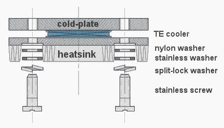
To install the module/s, follow these directions
1.) Spread a thin layer of thermally conductive grease (i.e. AOS 52022 or Dow Corning G340) in the location where the module will be seated on the heat sink. Place the module on the heat sink and gently move the module back and forth to squeeze out any excess grease.
2.) Spread a thin layer of thermal grease in the appropriate location of the cold plate, or object to be cooled, and place this onto the module (and heat sink). As above, gently remove any excess grease.
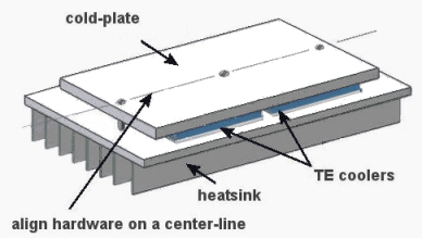
3.) Place all connecting hardware loosely into the sub-assembly. Beginning at the center evenly tighten connecting hardware by hand or until you meet slight resistance. In this example, you would begin with the middle screw located between modules on the module center line.
4.) Using a torque-limiting wrench, begin tightening in small increments from the center bolt outward.
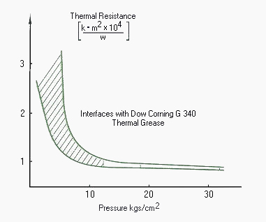
5.) As shown in the following figure (data by Dr. J.G. Stockholm) the thermal resistance and dispersion of thermal grease depends upon the pressure against the module ceramics and reaches a relatively low value at a pressure of 10 kgf/cm2. It is sufficient to provide pressure in the 10 - 15 kgf/cm2 range for acceptable and stable thermal contact. The torque per clamping screw (Type 4 - 40, 6 - 32 manufactured from stainless steel) should be no more than 0.11 kgm for modules having and area of 40 x 40 mm.
6.) After reaching the desired torque value, leave the assembly for one hour. Check torque and re-tighten as necessary.
Design Recommendations
Both the heat sink and cold plate should be sufficiently rigid to prevent any bowing or deformation when clamping your assembly together. If components are not sufficiently rigid, modules will not perform optimally and may be damaged. Aluminum components should not be less than 6 mm thick and copper components not be less than 4 mm. Clamping screws should only be located on the module/s center line. We recommend the clearance between module edges and bolt holes be 3 mm. If space does not allow this, you may increase the distance but not exceed 12 mm.
Finally, If your finished product will be operating at temperatures near, or below, the dew point, or if the equipment will be routinely turned off, condensation from components may become water that can enter the module. This moisture can cause corrosion leading to performance deterioration, or an electrical short. Adequate care should be taken to seal modules from moisture. We offer Epoxy and RTV edge sealing that consits of a bead of aircraft grade epoxy (or silicone RTV) around the perimeter of the module, and sufficiently far down the leads to prevent wicking ("E" suffix in part number for Epoxy, "RTV" for RTV). While both offer protection from condensation, Epoxy sealing is generally recommended because of its very low vapor permeability. (An Epoxy edge seal also provides a more concrete edge that helps to reduce damage to the ceramics during installation if a technician initially applies uneven clamping pressure.) Finally, both edge seals will reduce the ΔTmax as a result of a thermal bridge resulting from their application. The ΔTmax is reduced by 1-2 °C for Epoxy sealed modules and 2-3 °C for Silcone sealed modules.
Larger areas than an individual module can maintain are cooled, or have the temperature controlled, by using multiple modules. When multiple modules are used in an assembly sharing a common heat-sink, and object being temperature controlled (cooled), lapping the TECs to a close height tolerance will improve overall performance by making all the modules equally thick (within a thousandth of an inch). This will reduce gapping that may otherwise be caused by slightly thin modules.
Related Links:
sales@electracool.com
Toll free in North America: 1 866.665.5434
International: 603.888.2467