
This Is How Thermoelectric Coolers Works

A typical thermoelectric (TE) module is composed of two ceramic substrates sandwiching many pairs, or "couples" of Bismuth Telluride dice. The (pairs of) dice are connected electrically in series, and thermally in parallel, between the ceramics. One of these ceramics will be the "hot-side" and the other, the "cold-side."
Alumina ceramic substrates are commonly used for making TE modules. They're ridged, thermally conductive and excellent electrical insulators. In addition to providing a sturdy foundation, the ceramics insulate the electrical elements within the module from a heat-sink on the hot-side of the module, and the object being cooled on the cold-side.
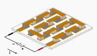
Pads of electrically conductive material, usually copper, just large enough to accommodate each of the many "pairs" of dice in a module, are attached to the inside surfaces of the ceramics. One of each of the P-type and N-type dice make an electrical connection with each pad. The layout of the pads on the two ceramics varies, to create a circuit, with the dice, that zigzags through the module. Typically all the dice are soldered into place to enhance the electrical connection and hold the module together.
Most modules have and even number of P-type and N-type dice and one of each, sharing an electrical interconnection, is known as, "a couple." The above module would be described as an 11-couple module.
While both P-type and N-type materials are alloys of Bismuth and Tellurium, both have different free electron densities at the same temperature. P-type dice are composed of material having a deficiency of electrons while N-type have an excess of electrons. As current (Amperage) flows up and down through the module it attempts to establish a new equilibrium within the materials. The current treats the P-type material as a hot junction needing to be cooled and the N-type as a cold junction needing to be heated. Since the material is actually at the same temperature, the result is that the hot-side becomes hotter while the cold-side becomes colder. The direction of the current will determine if a particular die will cool down or heat up. In short, reversing the polarity will switch the hot and cold sides.
Wire leads to the modules are attached to the (copper) pads on the hot-side ceramic. If the module is sealed you can determine the hot-side without applying power. With the module on a flat surface, point the leads toward you with the positive lead, usually in red wire insulation, on the right. The bottom surface will be the hot-side.
Material researchers are investigating the use of other materials to improve the efficiency of thermoelectric modules but Bismuth Telluride remains the most economical material for cooling modules used in ambient temperature applications. However, at low temperature (around minus 110 degrees Celsius) this material stops becoming a semiconductor and performance is severely diminished. Typically, the highest temperature that modules can operate is about 30 °C below the melting point of the solder used in its assembly, usually +150 or 200 °C (302 or 392 °F).
TM 127-1.4-8.5 is our most popular choice for most thermoelectric module power generation (TEG) applications, with temperatures up to 200 °C (392 °F).
Some Bismuth Telluride based modules for power generation applications are fabricated with high melting temperature solder or without solder entirely. Some of these may be used at temperatures up to +400 °C.
Related Links:
sales@electracool.com
Toll free in North America: 1 866.665.5434
International: 603.888.2467