Here's What You Need to Know
to Successfully Work with Thermoelectrics
Thermoelectric (TE) modules are solid-state devices (no moving parts) that convert electrical energy into a temperature gradient, known as the "Peltier effect" or convert thermal energy from a temperature gradient into electrical energy, the "Seebeck effect."
It's anticipated that thermoelectric generators (TEGs) may one day be used to take advantage of wholesale "waste heat" recovery for power generation, but contemporary TEGs remain rather inefficient. Improving the efficiency of the semiconductor materials used in thermoelectric generators is an area of substantial contemporary research but the total cost, per watt produced, is still generally more expensive than power available from the grid. There are applications where TEGs provide a sufficient amount of power to be the best choice for certain applications. These include supplying power to spacecraft with a radioisotope thermoelectric generator and for powering remote electronic equipment along fuel pipelines, where fuel is burned off to provide a source of heat. TM 127-1.4-8.5 is our most popular choice for thermoelectric module power generation (TEG) applications, with temperatures up to 200 °C.
This discussion will focus on the use of thermoelectric modules for cooling (as TECs) and for temperature stabilization.
With no moving parts, thermoelectric modules are rugged, reliable and silent heat pumps, typically 1.5 inches (40 x 40mm) square, or smaller, and approximately ¼ inch (4 mm) thick. The industry standard mean time between failures (MTBF) for TECs is around 200,000 hours, or over 20 years.
Thermoelectric modules require a DC (Direct Current) power source rather than AC (Alternating Current) that's widely distributed through the electric grid and delivered to wall outlets. AC-to-DC transformers, simply called "power supplies" or "PSUs" are most commonly used to provide the appropriate DC power for thermoelectric modules, and assemblies. The most widely used TE modules are powered with a 12 volt nominal power source though many modules are designed for operation at lower voltages, and a few higher. In some cases, batteries and battery chargers (without too much AC ripple) can also be used as sources of power for 12V nominal modules.
The cooling capacity for TE modules is linear to the voltage applied (up to the Vmax rating) so 15V supplies are occasionally used with our 12V nominal modules for enhanced performance. Most of the power supplies we sell have a rheostat allowing for ± 10% adjustment to the rated power, so 12V supplies can be turned up to 13.2V, and 15V supplies turned down, as desired. Most of our 12V nominal TE modules have a Vmax of 16V and that should not be exceeded.
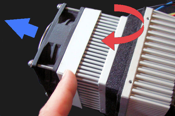
When the appropriate power is applied, one side of the module will be made cold while the other is made hot. Click here to see how they work. Interestingly, if the polarity, or current flow through the module, is reversed the cold-side will become the hot-side and vice versa. This allows TE modules to be used for cooling, heating and temperature stabilization.
Since TE modules are electrical in nature, in a closed-loop system with an appropriate temperature sensor and controller, TE modules can easily maintain temperatures that vary by less than a degree.
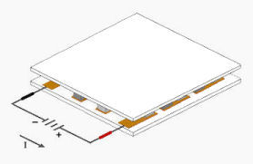
The footprint of a standard thermoelectric module is limited to about 2 inches square for reliability. There is a degree of thermally induced stress, at the electrical connection points, or "joints," inside every module as a result of the difference between the expansion and contraction of the hot and cold sides. As the surface area of the substrates increases, this divergence becomes more pronounced, and at a certain point, leads to a weakening the joints. It's noteworthy that the substrates, semiconductor dice and solder that make up a TE module all have different coefficients of expansion.
A standard 40mm square, 127-couple module has 254 dice. Each of the dice have solder joints to both the hot and cold-side substrates, for a total of 508 joints. The weakening of a single solder joint will cause a degradation in performance, typically leading to an electrical short. It's for this reason that large cooling modules are not common. Long, thin modules want to bow for the same reason and are also rare.
The effects of thermally induced stress are far more pronounced when a standard TEC is used for both heating and cooling, or "thermal cycling." It's easy to see that switching the contracting cold-side into the expanding hot-side would create more joint fatigue than a module left in a steady state. Two methods have been used mitigate the impact of thermally induced stress in TE modules for cycling. The first technique is to slice one of the ceramics into smaller pieces, providing partial relief by reducing the impacted surface area/s. The second method is to glue, rather than solder, the copper pads on one side of the module. The joints in this type of modules have the ability to flex and are the type we sell for cycling.
Larger areas than an individual module can maintain are cooled, or have the temperature controlled, by using multiple modules. When multiple modules are used in an assembly sharing a common heat-sink, and object being temperature controlled (cooled), lapping the TECs to a close height tolerance will improve overall performance by making all the modules equally thick (within a thousandth of an inch). This will reduce gapping that may otherwise be caused by slightly thin modules.
The two choices for connecting multiple modules are, in parallel (same input voltage with increased current) or in series (input voltage increases but current is reduced). A combination of the two, consisting of multiple parallel "strings," of modules connected in series, is common for managing large surface areas. From a design perspective, longer strings are usually comprised of modules with low to moderate Qcmax ratings. This is partly to limit the amount of heat ejected, but primarily because of the relative scarcity, and prices, for power supplies with high current ratings.
We know from the second law of thermodynamics that heat will move to a cooler area. Essentially, the module will absorb heat on the "cold-side" and eject it out the "hot-side" (to a heat-sink). The addition of a heat-sink to a module creates a thermoelectric device or assembly. In addition to the heat being removed from the object being cooled, the heat-sink must be capable of dissipating the electrical power applied to the module, which also exits through the module's hot-side. The total heat ejected by the module is the sum of the voltage times the current, plus the heat being pumped through the cold-side (up to Qcmax).
To understand the capabilities of a thermoelectric module, and related assembly, it is necessary to understand what TE module specifications represent and their implications.
The four standard specifications for a thermoelectric module are:
Qcmax is maximum cooling capacity, in watts (At Imax, Vmax and ΔT = 0 °C)
ΔTmax (or Delta Tmax) is the maximum achievable difference in temperature between the hot and cold sides of the TE module. (At Imax, Vmax and Qc = 0W)
Imax is the maximum current at ΔTmax
Vmax is maximum voltage at ΔTmax
In mathematical formulae, temperatures are typically expressed in Kelvin (K) units of measurement.
To make information more intuitive for the average user, we often use degrees Celsius (°C) as 1 K = 1 °C.
As a practical matter, it is only possible to reach either heat pumping capacity in watts, or to obtain the maximum temperature differential in degrees. In other words, the ΔTmax is the maximum temperature difference between the hot and cold sides of the module when optimal power is applied and there is no heat load (Qc=0). As a thermal load Q is added, the difference in temperature between the two surfaces will decrease until the heat pumping capacity or Qcmax value is achieved and there is no net cooling (ΔT=0). Since your application will likely require net cooling of an object with a thermal mass, the actual heat pumped, or Qc, will be less than Qcmax and the actual difference in temperature will be less than the ΔTmax.
We provide two sets of performance curves illustrating the relationships between power applied and net cooling for each ElectraCOOL™ thermoelectric module. The first, with Th=27 °C is appropriate for most applications. This set of curves is for those applications that will be operating in an ambient around 20 °C (70 °F). That’s approximately the temperature in most business and laboratory settings. There are a variety of reason that temperatures on the hot-side of the TE module may be higher including limited space for heat-sinking, marginal ventilation and outdoor applications. As a guide for those applications the second set of curves are prepared with a Th of 50 °C (122 °F).
To see the curves for a TE module, click on the appropriate TE module part number from our module specifications page and then click on the appropriate temperature curve at the bottom of that page.
After learning what power is required for an appropriate module to reach the desired level of cooling and heat pumping capacity, it is necessary to focus on the assembly required, specifically heat-sink selection, in order to allow the module to maintain the desired results.
The actual cold-side temperature, with a given level of cooling (ΔT or DT), is derived by subtracting the temperature of the cold-side Tc from the temperature of the hot-side Th.
A simplistic way to think of this relationship is to think of the ΔT as a sort of "thermal elevator," with the floor being the cold-side of the module Tc and the ceiling the hot-side Th. In the most common thermoelectric applications, ambient air is blown over a hot-side heat-sink to provide cooling. However, since heat is produced operating the thermoelectric module, the hot-side temperature will always be above the ambient temperature. Chillers can be used to provide below ambient cooling fluid to a liquid heat-sink. While this type of assembly is rare, the temperature of the cooled liquid will approximate the “floor” of the afore mentioned thermal elevator.
With a given ΔT in this "thermal elevator," for each degree that the hot-side rises, the cold-side rises by the same amount. Using a theoretically perfect heat-sink capable of maintaining ambient, and with a 40 degree ΔT, the cold-side would be 40 degrees below ambient. In actuality, the hot-side is always above ambient. If the hot-side is 10 degrees above ambient, the cold-side would be 10 degrees above the theoretical maximum, or 30 degrees below ambient (40-10=30). It's noteworthy that if in this example, the hot-side increases by more than 40 degrees above ambient, the cold-side will also be above ambient, yielding a net heater. The hot-side temperature of a TE module can quickly run away so never apply power until a TE module is installed.
In order to avoid disappointment with your assembly, it's critical to keep the hot-side as cool as possible in order to take advantage of the ΔT the module provides.
The most common mistake, made by the TE novice, is selecting a hot-side heat-sink based solely on a module/s heat pumping capacity or Qcmax.
A thermoelectric module is a sort of resistive dead-end so both Qcmax plus input power (volts x amps) must be added together to determine the total watts that may have to be effectively managed by the heat-sink.
Initially, it's natural to want to use a module with a high Qcmax however, the total amount of heat ejected can be significant and not appropriate for the application. For example, TM-127-1.4-8.5 is a powerful single-stage thermoelectric module with a Qcmax of 72 watts. However, with full power applied, the total heat ejected would be about 200 watts consisting of 72 watts (Qcmax) plus 125 watts of input power (15 volts x 8.5 amps). At a nominal 12V, the total is 137 watts (Qc of 65 watts plus 72 watts (12 volts x 6 amps) of input power.
If your application doesn't have sufficient space for optimal heat-sinking, or to allow for the TE assembly to direct the heat discharged to an environment capable of maintaining a relatively cool ambient temperature, the amount of heat produced may be a factor. For example, if the TE assembly is within a closed box, or if cooling a box within a box, you must consider that the heat discharged from the thermoelectric assembly will raise the air temperature inside the box, or the outer box. Without sufficient ventilation, this will result operation at a higher temperature than you may have expected (review the aforementioned "thermal elevator"), yielding correspondingly reduced cooling capacity. In these situations it may be appropriate to investigate less powerful TE modules for the application.
Computer enthusiasts seeking to overclock a computer by forcing a processor to operate faster than its manufactured clock frequency will find that most stock heat-sinks for this purpose are designed for an acceptable increase in temperature at the conventional speed (and power). Applying more power to a processor will increase the speed but also the thermal load presented to the heat-sink resulting in higher operating temperatures. The increase in temperature rise can cause instability and possibly damage the processor. Adding a thermoelectric module, like the one described in the previous paragraph, will increase the load from about 70 watts (without a TE module) to about 200 watts and the temperature of a stock heat-sink will run away, possibly dangerously. Generally we recommend a liquid-to-air radiator for this, and similar 'spot cooling' applications (see below).
This brings us to the importance of selecting an appropriate heat-sink for your application. In general, the better (the lower the thermal resistance of) the heat-sink, the easier it is to keep the hot-side temperature from increasing. It is recommended that you select the largest (greatest surface area) heat-sink that you can accommodate. In general, to reduce the thermal resistance of a heat-sink by 50% it is necessary to increase it's volume by 400%.
In most applications TE modules will be appropriate for, a heat-sink alone will not be able to remove a sufficient amount of heat, by natural convection, to keep the hot-side at an acceptably low temperature. In order to shed heat presented to a heat-sink, a fan or blower must be attached that forces ambient temperature air over the fins and exhausts that heat to back to ambient. This is known as a forced convection cooling and the following discussion of heat-sinks assumes the use of a fan or blower. As mentioned before, the hot-side temperature of a TE module can increase quickly so ensure that fans or blowers are running when applying power to the TE module/s in a thermoelectric assembly.
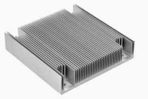
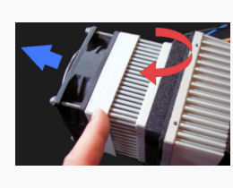
Extruded aluminum heat-sinks are readily available, economical and offer reasonably good cooling in applications with a relatively low thermal density. However, there are limitations to the number, height, and thickness of the fins that can be produced in the extrusion process. This is known as the fin height-to-gap ratio which can be as high as 6:1 for extrusions. Since the fins are uniform and parallel, there's marginal turbulence in the airflow through this type of heat-sink, limiting the effectiveness of heat transfer. It's common that the hot-side temperature of a TEC will stabilize at 5 - 15 °C above ambient in an assembly using a forced convection extruded heat-sink.
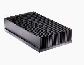
Better, but more expensive, is the bonded (or fabricated) fin heat-sink. A typical bonded fin heat-sink has a similar geometry to an extrusion, but is made from a base-plate with separate fins inserted into groves in the base-plate. The height, thickness and density of the fins can be extensively modified. This allows for a substantial potential increase in cooling surface area (lower thermal resistance) than is possible with an extrusion. By starting with a flat base-plate, footprint and fin size are not significant issues. It's common to have a fin height-to-gap ratio of 20 to 40, which greatly increases cooling capacity without necessarily increasing volume, compared with an extrusion. This flexibility allows package designers to select, or have built, a heat-sink that enhances the heat dissipation part of their assembly.
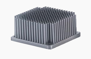
Pin-fin heat-sinks have several hundred individual pins inserted into a base-plate. A substantial amount of turbulence is created in the airflow though this style of heat-sink yielding excellent performance. Air blown into this type of heat-sink is exhausted out all four sides, reducing the distance warm must travel before being returned to ambient. There are manufacturing limitations to the footprint size of this type of heat-sink,
 topping out at around 4" (100 mm) square. A temperature rise of just a few degrees above ambient is typical.
We use this type of heat-sink in many of our standard TE assemblies.
It's sometimes desirable, to direct the cold-side airflow away from our air conditioners. For example, you might like to move cooled air some distance within an enclosure, improve temperature uniformity, spot cool or force cooled air through a duct. This is easy to do on our air conditioners by flipping over the cold side fan. For enhanced performance a fan shroud can be added that creates a space between the heat-sink and fan where a slight vacuum is formed, enhancing turbulence, and heat transfer.
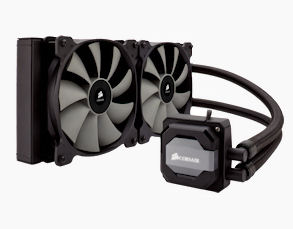
Liquid heat-sinks generally have the lowest thermal resistance but are often the most complicated, when plumbing and cooling the liquid is involved. For many single module applications however, there are a variety of liquid-to-air 'radiators' readily available, that offer an excellent solution for thermoelectric "spot cooling." This method exhausts to ambient the heat from both the item cooled and the TEC. The CORSAIR Hydro Series, designed for CPU cooling, are economical ($150 and less), compact, and completely self-contained. We have found that with slight modifications to the stock installation hardware provided, mounting to appropriately machined plates is relatively uncomplicated. We also recommend using higher speed fans than are provided, if possible, to enhance cooling through the radiator.
When installing TE modules in an assembly, it's most common to compress, or "clamp" them between a forced convection heat-sink on the hot-side and something to be cooled. The object cooled can be a block of metal creating a cold plate, another forced convection heat-sink making an air conditioner, or a liquid heat-sink forming a liquid-to-air exchanger. Liquid-to-Liquid exchangers can also be made, and are similarly installed.
Related Links:
sales@electracool.com
Toll free in North America: 1 866.665.5434
International: 603.888.2467