
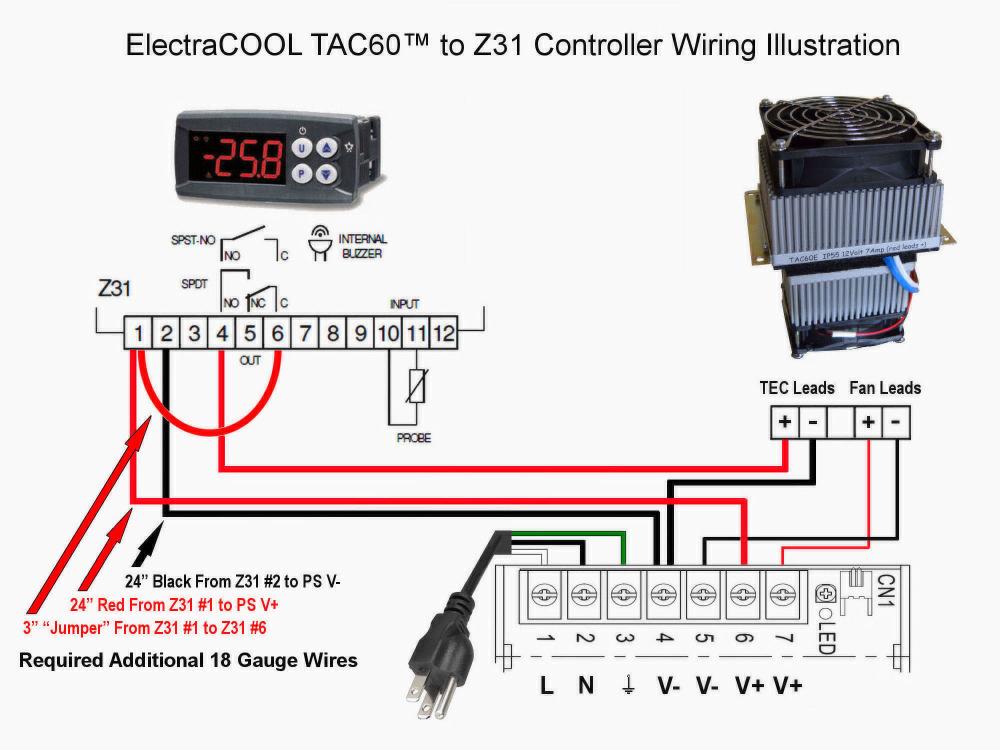
Optimize Your TAC60™ Performance & Simplify Maintenance
Mounting Considerations & Instructions:
Determine the best location to mount your TAC60/s. Since heat rises, it’s common to mount them on the top of an enclosure or in a door, near the top.
Door mounting provides easy access to the interior fan for servicing, without removing the TAC60™ from the enclosure.
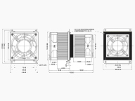
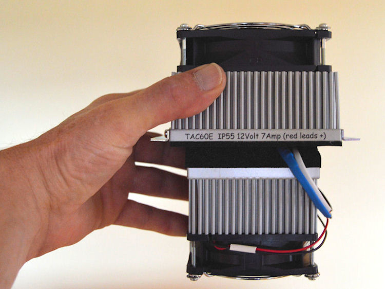
When installed, the larger four inch (100mm) wide “hot-side” of the TAC60™ will remain on the outside of the enclosure. Approximately ½ inch around the perimeter of this heatsink rests against the exterior wall. The smaller three inch wide (80mm) “cold-side” will be entirely inside the case. The cold-side intrudes 3.25 inches (83mm) into the case, from the OUTSIDE wall of the enclosure, so allow sufficient clearance within.
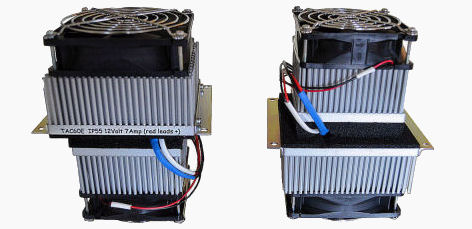
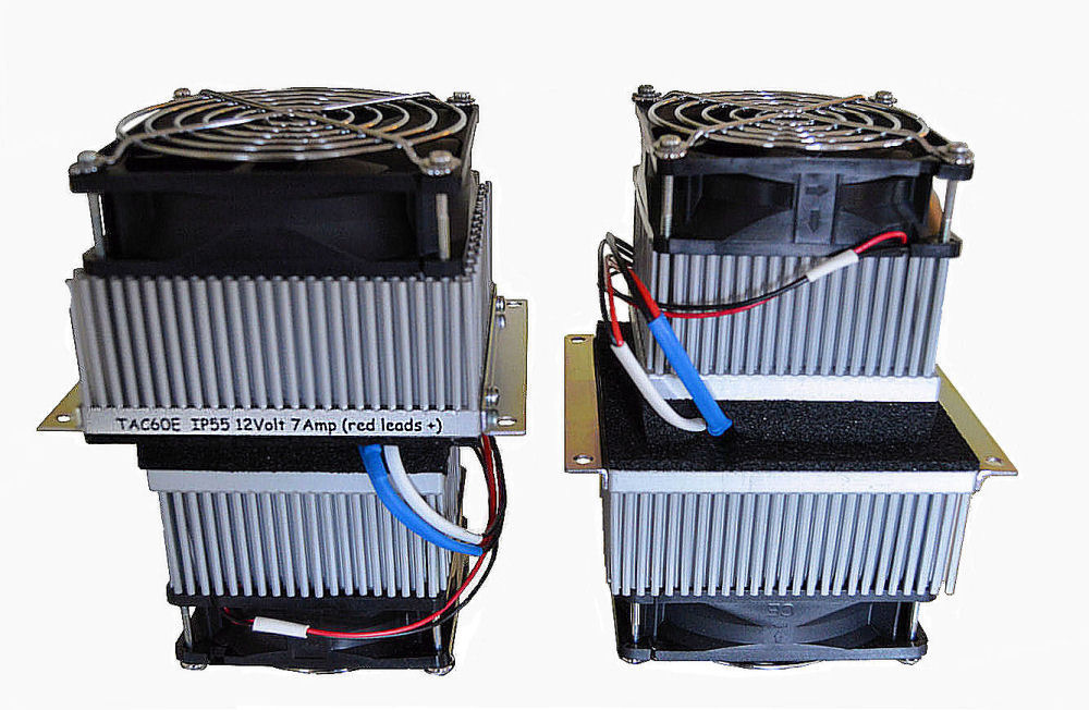
The left image shows a TAC60™ with Hot-Side up. On the right, the TAC60™ has been flipped upside-down and the Cold-Side is at the top.
When mounted, the Hot-Side will be entirely outside of the enclosure while the cold side will be within.
After determining ideal placement, mark and cut a 3.2 inch (82mm) square hole through the enclosure wall. Starting with the wires, pass cold-side of TAC60™ through the wall. Be sure to keep the wires close to the cold side heatsink and gently fit into place. There is a little space for play at this point, so look closely to confirm the exact placement of the TAC60™.
For outdoor applications, or when the TAC60™ will be mounted perpendicular to the ground (door or side wall mounting), the TAC60™ is generally installed with the “L” brackets vertically aligned (pointing up/down). This will keep water from collecting on, or behind, an “L” bracket.
When satisfied with TAC60™ positioning, mark the enclosure wall at the location of each of the four holes in the “L” brackets on the TAC60™. Remove the TAC60™ and drill holes through the wall of the enclosure where you have marked. The holes drilled should be just large enough to accommodate the hardware you choose to attach the TAC60™ to the enclosure.
We recommend using 6/32 ½ to ¾ inch long stainless steel, Phillips pan head, machine screws with matching nuts. The screw length depends on the thickness of the enclosure wall. Use ½ inch long screws for sheet metal enclosures and ¾ inch for fiberglass, plastic or composite material that’s approximately 1/4 inch thick. (Consider the following section on insulation.)
If possible, it’s ideal to drill then ‘tap’ threads though the enclosure walls. This allows you to screw through the enclosure wall when mounting, making a more water-tight connection around the screws.
If you’re building multiple boxes, make a template now.
With the TAC60™ in the desired location, place all connecting hardware loosely into place. In order to obtain a water-tight seal, it’s important to compress the neoprene gasket that's on the hot-side heatsink evenly against the exterior of the enclosure. Evenly tighten each screw by hand until you meet slight resistance. Then tighten each bolt or screw ½ turn at a time until sufficiently secure.
There may be a slight amount of play as a result of the holes in the L-bracket being larger than the connecting hardware. Check alignment after you begin tightening.
You will want the neoprene gasket sufficiently compressed against the enclosure wall to maintain a dust or water-tight seal. Tighten the connecting hardware very firmly if the enclosure is made of metal but if it’s made of material like plastic, fiberglass, or a composite material be careful not to over tighten as it may cause cracking.
Insulation:
The use of insulation is important in many applications, particularly with outdoor installations and when you desire an internal case temperature below ambient. In order to have the TAC60™ operate as effectively as possible, you want reduce the amount of heat passing through the walls of the enclosure. Space for insulation is typically limited in an enclosure but a variety of products are available that will make a big difference.
The average enclosure can be reasonably well insulated using Foam Board or Rigid Foam Panels available at most home improvement stores. They provide good thermal resistance, reducing heat conducted into the enclosure. The most common types of foam board include polystyrene, polyurethane and polyisocyanurate (polyiso).
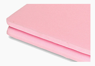
We recommend using Extruded Polystyrene (XPS). Easily recognized by its blue, pink, or green color, XPS falls in the middle of the three types of rigid-foam insulation in both cost and R-value. Readily available at local stores in ½ inch thickness (with an R-Value of approximately 3.0), XPS is easy to cut and install. Since air can go around but not through this insulation, fit corners snugly and seal or tape the seams. Note that most XPS Foam board insulation is flammable. While this insulation is difficult to ignite, do not do not use near an open flame, or close to heat sources above 150ºF (66ºC). Be aware of, and follow, local, national and OSHA guidelines and regulations.
Ultimately, the entire enclosure should be insulated.
The procedure for insulating the door, or wall, you will be mounting the TAC60/s:
1.) Test fit the TAC60™/s
2.) Prepare the insulation
3.) Mount the TAC60™/s
4.) Install the insulation.
1.) After the enclosure has been prepared for mounting the TAC60™/s, as described above, remove them from the enclosure.
2.) Size and place a piece of insulation against the inside of the appropriate door, or wall, of the enclosure.
Generally this piece of insulation should not exceed ½ inch in thickness. Thicker insulation may restrict the airflow around the internal (cold-side) heatsink/s severely reducing performance. We specifically like Owens Corning FOAMULAR® Half-Inch extruded polystyrene (XPS)
From the outside, mark the insulation with the location of the square hole/s to pass the TAC60™/s through, as well as the location of the four holes for the hardware attaching each TAC60™.
Remove the insulation from the enclosure and cut the square hole/s in the insulation at 90 degrees. Drill a shallow hole in the insulation, approximately ¼ deep for each of the four holes for connecting hardware. These holes should be large enough, and just deep enough, to fit around the nuts holding the connecting hardware in place, but no larger.
3.) When everything has been prepared, re-install the TAC60™/s to the enclosure wall.
4.) Put a small amount of adhesive on the inside of the door or wall of the enclosure sufficient to hold the insulation in place. Typically adhesive is put in the corners and in a circle two or three inches away from perimeter of the square hole/s for the TAC60™/s.
Pass all wires through the appropriate square holes in the insulation then place the insulation in over the cold-side of the TAC60™/s.
With both hands gently press the insulation against the door/wall. Start at the location of the connecting bolts or screws close to the TAC60™/s. The insulation may have to be pushed over the ends of mounting bolts or screws. When the insulation has made good contact with the wall, move to the corners.
If you must use screws or bolts that intrude into the case, beyond the insulation, cut them flush with the insulation and tape or seal over the ends.
Any additional insulation on this wall should start 3 or more inches away from the TAC60™ for adequate air flow.
Insulate the rest of the enclosure as well as possible. Tape or seal seams and joints.
Fan Replacement or Repair:
The TAC60™ has been designed so that fans can be easily replaced. Remove the four screws holding the fan and fan (finger) guard in place, and pull the fan away from the assembly.
On the smaller cold-side of the TAC60™, you can simply exchange the fan and re-attach with the fan guard and four screws.
On the hot-side, the fan lead wires pass through the heatsink. There is enough slack in the leads to have room to work, typically about 6 inches. The slack wire is tucked into a channel in the heatsink and held loosely in place with several heatsink pin fins. Slide these pin fins back to allow access to the leads then pull the fan away from the assembly. Cut the existing connector out where the leads from the heatsink meet the connector, and remove the fan. Strip ¼ inch off the existing leads then cut and strip the fan leads to maintain similar lengths to the fan removed. Reverse the order for installation of the new fan.
We recommend using shrink wrap over crimped non-insulated butt connectors for 22-18 AWG stranded Cu wire such as 3M’s terminal HT-61. Slide a 1 ½ inch length of shrink wrap, like RayChem RNF100 1/8 inch expanded, over each of the new fan leads. Crimp the red lead from the fan with the red lead from the TAC60™. Center the shrink wrap over the butt splice and use a heat gun to shrink the material until there is no more contraction. Repeat the process with the black leads.
Place the fan close to its mounting position and insert any slack in the leads back into the channel in the heat sink. Push the pins back to hold the wires loosely in place. Inspect to make sure that nothing will interfere with the fan blades being able to spin. Re-attach the fan guard and four mounting screws to hold the fan in place.
If you need a replacement fan, or if you have any difficulty, please feel free to contact us.