
Z31-A GS (12~24 VAC/VDC)
Single Set-Point Temperature Controller
Z31-A User Manual (.pdf download)
Z31A-GS is a single set-point digital microprocessor based temperature controller for Cooling or Heating applications. This instrument, with an ON/OFF control mode, has one 16 amp relay output (SPDT). We include an NTC 103AT-2 (10 kΩ at 25 °C) sensor, that can be configured. Tecnologic's replacement for the TLZ10 & TDH01 line of controllers.
See the tabs below for programming and wiring instructions.
The Z31-A Series is a replacement for the TLZ10 and TDH-01 Series. The new Z31-A version is identical in size and functionally to the older models, including having a 16 amp SPDT Relay output however, the list of parameters has been slightly modified. The Z31-A DOES NOT have defrost or buzzer functions. Buyers seeking a replacement for an original TLZ10 or TDH-01 should check the Z31-A User Manual to ensure that it has the functions (parameters) they require.
Z31A-GS Temperature Controller
Z31A-GS is a 12~24 VAC/VDC digital, microprocessor based, temperature controller for cooling or heating applications with a single set-point temperature and an ON/OFF control mode. The instrument has one 16 amp relay output (SPDT) and one input for NTC or PTC temperature probes, that can be configured. The instrument is equipped with 4 programming keys, a 3-digit display and 1 LED signal.
Other characteristics of the instrument are: Programmed parameters may be protected by using a personalized password, parameters can be uploaded from a programmed unit via the optional A01 device then downloaded to multiple units for quick programming...
We include an NTC 103AT-2 (10 kΩ at 25°C) thermistor.
We now have a limited number of Z31 HS E (100-240VAC) controllers in stock, priced at $159.
Other available Inputs: 12 VAC/VDC (F type). Contact us for availability: sales@electracool.com
* The Z31 Series replaces both the recent Tecnologic TLZ10 and older TDH01 Series. For legacy customers, wiring for the Z31-A is identical to the TLZ10 however, there are differences with programming.
Z31A-GS Specifications
1 probe input, 1 relay output and buzzer
Power Supply: 12~24 VAC/VDC ± 10% F: 50/60 Hz
Power Consumption: 4 VA
Input: Includes an NTC 103AT-2 (10 kΩ at 25 °C) sensor. Will work with a PTC KTY 81-121 (990 Ω at 25 °C) sensor
Keyboard: Mechanical ("Sensitive-Touch" type available)
Measurement range: NTC: -50...109 °C / -58...228 °F; PTC: -50...150 °C / -58 ... 302 °F
Output: One (1) 16 amp relay output SPDT 16A-AC1 (12 A max for each terminal with extractable terminal block)
Case: Self-extinguishing plastic, UL 94 V0
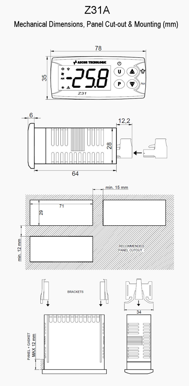
Dimensions: 1/16th DIN, Front Panel 35x75 mm, Depth 64 mm (+ 11.5 mm with extractable terminal block)
Weight: 120 grams approx.
Mounting: Incorporated Flush in panel (thickness max. 12 mm) in 71 x 29 mm hole
Connections: 2.5 mm² screw terminals block or 2.5 mm² extractable screw terminals block for 0.2...2.5 mm² / AWG 24...14 cables.
Degree of protection from panel: IP 65 (NEMA 3S), mounted in panel with gasket
Control: ON/OFF, Stand-By mode
Display resolution: 1 ° or 0.1° (range -99.9 ~ 99.9 °)
Overall Accuracy: ± 0.5% fs + 1 digit
Sampling rate: 130 ms.
Communication and configuration: Universal Programming Key on TTL port
Compliance: European RoHS Directive 2011/65/EU, Directive 2004/108/CE (EN55022: class B; EN61000-4-2: 8KV air, 4KV cont.; EN61000-4-3: 10V/m; EN61000-4-4: 2KV supply and relay outputs, 1KV inputs; EN61000-4-5: supply 2KV com. mode, 1 KV\ diff. mode; EN61000-4-6: 3V); Directive 2006/95/CE (EN 60730-1, EN 60730-2-9). Regulation 37/2005/CE (EN13485 air, S, A, 2,- 50°C +90°C with probe NTC 103AT11).
Also available with extractable terminal block and "Sensitive Touch" keyboard.
COMMUNICATION ON TTL PORT TO:
- Universal programming key (optional)
- Remote display (optional)

UL File no. E212227
Ref. UL/CSA 60730-1-2-9
Other available Inputs: 12 VAC/VDC (F type) and 100...240 VAC (H type). Contact us for availability.
Z31-A Temperature Controller Photos (Click image for enlargement)
-
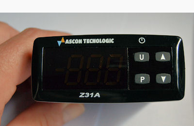
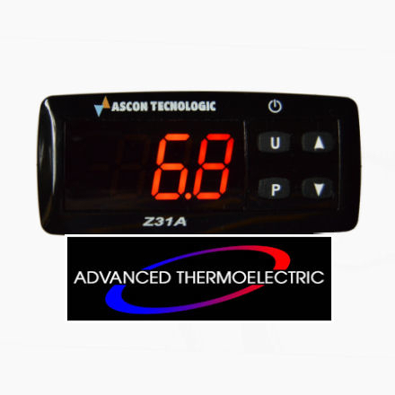 Z31-A Display
 -
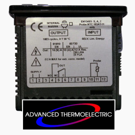 Z31-A Top Label Photo
 -
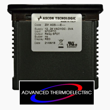 Z31-A Bottom Label Photo
 -
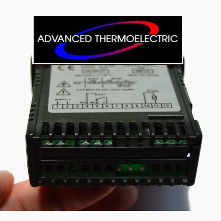 Z31-A Terminal Strip Photo
Mechanical Dimensions, Panel Cut-out & Mounting
Basic Z31-A User Guide - For use with ElectraCOOL™ assemblies
The following Z31-A User Guide is intended to assist with the most essential and common programming requirements when used with our thermoelectric assemblies. The guide is exclusively for use with the Z31-A (Z31 model A) temperature controller.
FAST PROGRAMMING OF A SET-POINT
The set-point temperature is the only value that can be changed without entering the comprehensive Programmable Parameters menu.
Generally, we preset controllers included with ElectraCOOL™ thermoelectric sets and assemblies, to a set-point temperature of +4 °C, in the cooling mode.
Press the "P" button for a moment then release it. The display will show “SP” alternating with the current set-point temperature. To change the temperature, press the UP key to increase the value or DOWN to decrease it. When the desired temperature is displayed, press the "P" button to memorize the new temperature and exit from the Set-Point programming mode. The display will return to the normal function mode if no key is pressed for about 10 seconds.
Z31-A Programming Overview
The programmable functions or “parameters” for the Z31-A controller are arranged in 7 primary groups. When in the programming mode, each group will be indicated by a letter (capitol or lower case) followed by a “.” The entire list of parameter groups, and the order they will be displayed on the controller, follows:
S. - parameters relative to Set Point
i. - parameters relative to inputs
r. - parameters relative to temperature control
d. - parameters relative to defrosting control (The Z31-A doesn't have the parameters for defrosting)
P. - parameters relative to compressor protection and power on delay
A. - parameters relative to alarms
t. - parameters relative to configuration of the keyboard
Each of these primary groups has several items or variables that can be changed. The complete list of all these items, and the default values for them, is shown in the Programmable Parameters Table, Section 5, of the factory Z31-A User Manual (.pdf download)
To modify any parameter value, open the main menu by holding down the “P” button until the LED display flashes (about 5 seconds). Using the DOWN key, scroll through the primary groups (listed above) until the desired group is displayed. Press the “P” button to enter that group.
Once within a primary group, you may similarly find the specific item to modify by using the up or down keys to scroll through the options available. Once the item to modify is displayed, push the “P” button and the currently programmed value for that item will be displayed. To make a change, simply push the up or down keys to see the other options available for that item, or to increase/decrease the value. Once the desired value has been selected, or entered, press the “P” again. The new value will be memorized and the display will show only the code of that parameter.
Pressing the UP and DOWN keys, it is possible to select another parameter and change it, as described above.
When programming is complete, press the “U” button for 2 seconds or don’t press any key for about 30 seconds and the controller will automatically exit the programming mode. The display will return to the normal function mode displaying the current temperature with LEDs indicating operational activity.
CALIBRATION OF THE Z31-A
ElectraCOOL™ Cold-Plate Sets have already been calibrated.
It’s sometimes desirable to calibrate the Z31-A with a new input probe or “sensor” to most accurately match the desired set-point with the actual temperature of the item being temperature controlled. The difference can be as much as 2 °C.
After the item has been running, and reached a steady-state temperature, measure the actual temperature of the item with separate accurate thermometer (i.e. hand held infrared). Note the difference between the actual temperature and the set-point temperature.
Adjusting The Probe Calibration Parameter.
Hold down the “P” button for about 5 seconds until the LED display flashes and the code that identifies the first parameter group “S.” is displayed.
Using the DOWN key, select the Inputs parameter group (2nd group down) when “i.” is displayed, by pressing the “P” button. With the UP or DOWN key select the Probe calibration parameter “ i.C1” and press the “P” button. The display will show the current value. The factory default of is 0.0.
Using the UP or DOWN key, change that value to the temperature difference observed between the actual and the set-point temperatures. Note, this is often a negative value. Once the desired adjustment has been made, press the “P” again to memorize the new value.
Press the “U” button for 2 seconds or don’t press any key for about 30 seconds and the controller will automatically exit the programming mode.
NOTE: The Z31-A typically ships from the factory configured to allow for a two (2.0) degree temperature differential between set-point and activation. This reduces the total number of starts, may extend the life of the controller, and the temperature variation is often within an acceptable range for refrigeration.
If your requirements necessitate tighter control, you can reduce the acceptable differential to as low as zero. Push and hold the "P" button until the LEDs flash and "S." is displayed. Then push the down arrow twice, until you see the “r.” indicating the parameter group for Temperature Control. Push the "P" button. The first item displayed, "r.d" indicates the Differential or Hysteresis parameter. Push the "P" button to display the current differential. The default value is “2.0” degrees. Push the down arrow until "0" or "0.0" is displayed. Push the "P" to memorize the new value. Push the "U" button for two seconds, or leave the controller alone for about 15 seconds, and the controller will be re-programmed with no differential.
CONFIGURING THE Z31-A FOR WARMING
The Z31-A can be programmed for either cooling (anything below ambient) or heating (anything above ambient), but not both simultaneously. Since most customers use our thermoelectric assemblies for cooling, by default the controller is set for operation in the cooling mode.
If you would like to use the Z31-A for warming with an ElectraCOOL™ assembly, the controller must be re-programmed for heating and the polarity to the thermoelectric modules reversed.
To Program or Re-program the controller for Heating:
Hold down the “P” button for about 5 seconds until the LED display flashes and the code that identifies the first parameter group “S.” is displayed. Push the down arrow 2 times until you see "r." (indicating the temperature control parameter group). Push the "P" button. Scroll through the parameters until you see "r.HC" displayed indicating the heat or cool parameter. Push the "P" button and the current value, either “C” for cooling or “H” for heating will be displayed. If necessary, use the up or down arrow until "H" is displayed. Leave the controller alone for about 15 seconds, and the controller will be re-programmed for warming.
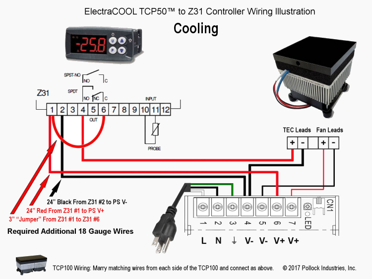
Wiring The Z31-A for Heating with an ElectraCOOL™ assembly: (also see Wiring Illustrations tab above)
If wiring a new assembly, connect the black lead/s from the TE/s to post 4 on the Z31-A and the red lead/s from the TE/s to a NEGATIVE (-) post on the power supply (to change the polarity). Make all other connections to the Z31-A and power supply, as described and illustrated above (red to + and black to -) for cooling above.
If you have the Z31-A configured for cooling, the red, positive leads are in post position 4 of the Z31-A and the negative leads are connected directly to the power supply. To switch polarity you can simply switch these connections. Remove the black lead/s from the negative post on the power supply and insert them into post 4 on the controller. Place the red leads removed from post 4 of the controller to the same (negative) post that the black leads were removed from. Leave all other connections alone (as per the instructions and illustrations for cooling).
SENSOR ERROR (E1)
The Z31-A may be used with either a PTC or an NTC type sensors. If you have a new controller, or sensor, and get an (E1) sensor error, you probably have the wrong type of sensor selected.
To determine what sensor the controller is currently programmed to operate with, and make a change if necessary, push and hold the "P" button until the LEDs flash and “S.” is displayed. Push the down key once and “i.” for Input Parameter Group will be displayed. Push the “P” button and the first parameter displayed should be “i.SE” for Input Sensor. Push the “P” button again and you will see the current value for the type of sensor.
If "PTC" is displayed, push the down arrow and "NTC" will be displayed and vice versa. Press the “P” button to memorize the new sensor type. Leave the controller alone for about 15 seconds, and the controller will be re-programmed for use with the alternative sensor type.
If the E1 message continues, you likely have a damaged PTC or NTC sensor that will need to be replaced.
PARAMETER PROTECTION USING A PASSWORD
If you’re concerned with tampering, the Z31-A has a parameter protection function that allows the use of a personalized password (number).
To program the controller to use this feature, hold down the “P” button for about 5 seconds until the LED display flashes and the code that identifies the first parameter group “S.” is displayed. Push the down arrow until you see "t." (indicating the keyboard parameters group). Push the "P" button. Scroll down until you see “t.PP” displayed, indicating the Password Parameter (parameter #25 in the user manual). Press the “P” button to display the current value “oF” indicating there is no password set. Using an up or down arrow key, select a value between -999 and +999 to be used for the password. With the desired value displayed, push the “P” button to program the controller with the new password.
When password protection is activated, press the “P” key for about 5 seconds, after which the display will show “r.P” . At this point, press the “P” key again and the display shows “0.” Using the UP and DOWN keys, enter the password number you’ve programmed and press the “P” key. This will take you to the first Parameter.
RESET PARAMETERS TO DEFAULT VALUE/LEVEL
The instrument allows the reset of all parameters to the original factory defaults.
To restore the Z31-A to the original default values, set the value -48 in the “r.P” password request. Confirm the password change by pushing P key and the display it shows "---" for 2 seconds. This indicates the instrument parameters have been reset.
KEYBOARD LOCK FUNCTION
To prevent unauthorized tampering you may completely lock the Z31-A keyboard.
To activate keyboard locking set the parameter “t.Lo” to a different value than oF.
Push and hold the "P" button on the Z31-A until the LEDs flash. Push the down arrow times until you see "ti," (indicating keyboard functions). Push the "P" button again then the down arrow until and "t.Lo" is displayed. Push the "P" button again. Select a positive value to be used for unlocking with the up arrow. When the number has been set, push the “P” button again to program the controller.
Not pressing any key for the time you’ve set in "t.Lo" the instrument automatically disables the normal functions of the keys. When the keyboard is locked, if any of the keys are pushed, the display will show “Ln” to indicate the active lock.
To unlock the keyboard, simultaneously push the P and UP keys for 5 seconds, after which the label “LF” will appear on the display and all the keys will function.
Z31-A Controller and ElectraCOOL™ Assembly Wiring
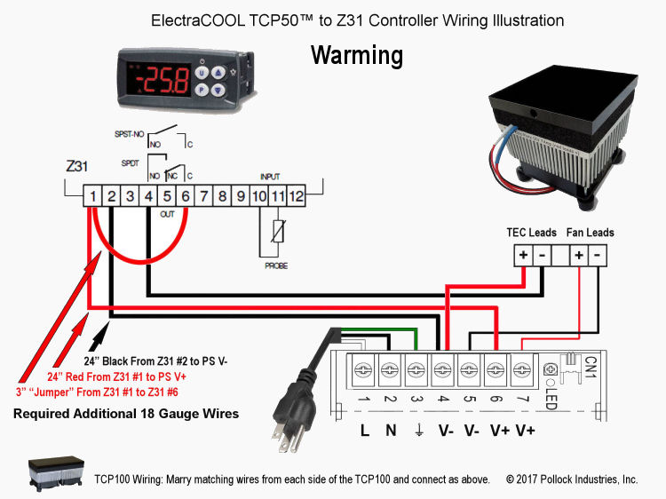
WARMING Mode
For warming, reverse polarity to the TEC/s.
Connect the black lead/s from the TE/s (heavier gauge than fan leads) to Z31-A slot 4, marked "NO" for Normally Open. Then connect the red lead/s from the TE/s to a NEGATIVE (V-) post on the power supply (to change the polarity). Make all other connections to the Z31-A and power supply, as described and illustrated below (red to + and black to -).
toll-free: 1 866.665.5434
Exports are generally shipped FedEx collect.
USPS International Express and Priority Mail available Pre-Paid.
For assistance contact: sales@electracool.com