ElectraCOOL™ TAC60™ Wiring Instructions with the Z31-A Controller
Caution! Risk of electric shock. The Z31-A temperature controller and our ElectraCOOL™ TAC60 enclosure air conditioners are designed for operation from a 12 or 24 Volt DC power source (such as the AC-to-DC power supply you may have purchased). Do not connect the Z31-A or a TAC60 directly to an AC source such as a wall outlet. If your power supply has a manual switch, make sure that the switch is in the correct position. In North America the switch should be set to 110 (or 115), and in Europe 220 (or 230).
The Z31-A is now the standard temperature controller included with our TAC60 and TAC60 Air Conditioner Sets. It’s easy to use and provides accurate control for cooling or warming. If you have selected the dual set-point TLK38-S see these instructions.
If you’ve purchased an ElectraCOOL™ TAC60 Set, we taken care of setting things up. Simply plug-in and your air conditioner is ready work. By default, the Z31-A is configured for cooling with a set-point temperature is 30 °C (86 °F) however, set-point modifications are quick and easy with the Z31-A.
Starting from scratch or want to switch things around? The following step-by-step instructions are all you’ll need. To use the Z31-A for HEATING see the bottom of this page.
For simplicity we illustrate and describe the connection process with the Z31-A controller and our standard PS-RSP150W power supply. Other power supplies, with the appropriate DC output, may be used by simply making the appropriate connection to Positive (+) or Negative (-) terminal posts as illustrated and described. Two TAC60s use the RSP320W power supply in either 12V or 24V depending on your desired configuration.
Be sure that the power supply in not plugged in until the entire controller wiring process has been completed.
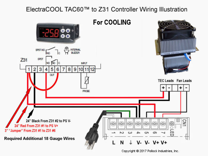
See the wiring schematic for cooling below. You will need a small Phillips head screw driver and three additional pieces of wire. Use 18 gauge wire to make all connections. Find one red and one black wire about two feet long and a three inch long red “jumper” wire.
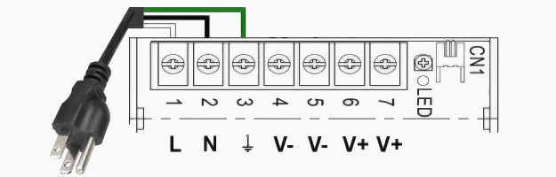
1. Connect the Power Cord to the Power Supply
To attach the 3-prong power cord, first locate the three terminal posts for (AC) input on the terminal strip of the power supply. Typically these are the first three posts on the left hand side of the power supply. Connect the white wire from the 3-prong power cord to the 1st post marked “L” and the black wire to the 2nd or negative post marked “N.” Finally connect the green wire to the post marked “FG” or with the ground symbol, in the 3rd terminal post position. You may test the connections by plugging in your supply and observing the led glowing. Unplug the power supply until you have connected the fans.
Typically there are two pairs (4 posts, numbered 4-7) of DC Output terminals on our power supplies rated for 300 Watts or less. Two adjacent posts are marked “–V” in positions 4 and 5 and those marked “+V” in positions 6 and 7. Use posts numbered 4 and 6 (V- and V+) as a pair and post 5 and 7 as a pair. Red wires connect to V+ and black wires to V-.
2. Connect the Fan/s
Each TAC60™ has two fans, one on the hot-side and one on the cold-side. Each fan has a red (+) and black (-) lead. The fan leads can be identified with white shrink wrap and having narrower wire than is used for the TECs (with blue shrink wrapping).
Connect the red fan lead/s directly to V+ post 7 on the power supply and the black fan lead/s to V- post 5. Confirm that you have the fan leads correctly attached by plugging in the power cord and observing the fans spin. If the fans are not spinning, unplug the power cord and check the previous instructions then, if unsuccessful, call or e-mail us.
We recommend connecting fans directly to the power supply so that they are supplied a constant, nominal 12 Volts. If fans are connected within the loop that’s temperature controlled, the fans may not supply enough airflow to keep the hot-side heatsink cool.
3. Connect the Z31-A Temperature Controller
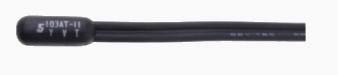
Connect the 1.5 meter (59 inch) long NTC sensor, that's included with the Z31-A. This type of thermistor can be shortened to 1 ft. (38 cm) in length but calibration (see instructions below) is advised.
The two NTC leads go into Z31-A slots 10 and 11. There is no + or - for the sensor leads so either wire can go in either slot. When all preparation have been completed, you will place the actual sensor (on the other end of the wire, with a bullet shape) at a location in the enclosure that you would like to measure the temperature.
On the Z31-A, slots 1 and 2, marked “SUPPLY” and are for DC power input from the power supply. Connect one end of a 24” spare piece of 18 gauge red wire to slot 1 in the Z31-A and connect the other end to the +V output at post 6 on the power supply. Next connect a 24” spare piece of 18 gauge black wire to slot 2 on the Z31-A and the other end to the –V output at post 4 of the power supply.
Using a 3” spare piece of (red) wire make a “jumper” from Z31-A slot 1 (also connected to the power supply) to the Z31-A’s terminal slot 6 (common of SPDT switch).
From the TAC60, select the pair of leads exiting with blue shrink wrap. These leads are for the thermoelectric module/s inside the TAC60. Connect the red, positive lead/s to Z31-A’s slot 4 identified by “NO” (meaning the normally open circuit of the SPDT relay). Finally, connect the black, negative lead from this pair to –V terminal post 4 on the power supply (not the controller).
4.) Power up and Program the Z31-A
You may now plug in the power cord and begin the programming of the Z31-A for your application.
Basic Z31-A User Guide - For use with ElectraCOOL™ assemblies
The following Z31-A User Guide is intended to assist with the most essential and common programming requirements when used with our thermoelectric assemblies. The guide is exclusively for use with the Z31-A (Z31 model A) temperature controller. Click to see the complete Comprehensive Z31-A User Manual.
FAST PROGRAMMING OF A SET-POINT
The set-point temperature is the only value that can be changed without entering the comprehensive Programmable Parameters menu.
Generally, we preset controllers included with ElectraCOOL™ thermoelectric sets and assemblies, to a set-point temperature of +4 °C, in the cooling mode.
Press the "P" button for a moment then release it. The display will show “SP” alternating with the current set-point temperature. To change the temperature, press the UP key to increase the value or DOWN to decrease it. When the desired temperature is displayed, press the "P" button to memorize the new temperature and exit from the Set-Point programming mode. The display will return to the normal function mode if no key is pressed for about 10 seconds.
Z31-A Programming Overview
The programmable functions or “parameters” for the Z31-A controller are arranged in 7 primary groups. When in the programming mode, each group will be indicated by a letter (capitol or lower case) followed by a “.” The entire list of parameter groups, and the order they will be displayed on the controller, follows:
S. - parameters relative to Set Point
i. - parameters relative to inputs
r. - parameters relative to temperature control
d. - parameters relative to defrosting control (The Z31 model A doesn't have defrosting parameters)
P. - parameters relative to compressor protection and power on delay
A. - parameters relative to alarms
t. - parameters relative to configuration of the keyboard
Each of these primary groups has several items or variables that can be changed. The complete list of all these items, and the default values for them, is shown in the Programmable Parameters Table, Section 5, of the factory Z31-A User Manual (.pdf download)
To modify any parameter value, open the main menu by holding down the “P” button until the LED display flashes (about 5 seconds). Using the DOWN key, scroll through the primary groups (listed above) until the desired group is displayed. Press the “P” button to enter that group.
Once within a primary group, you may similarly find the specific item to modify by using the up or down keys to scroll through the options available. Once the item to modify is displayed, push the “P” button and the currently programmed value for that item will be displayed. To make a change, simply push the up or down keys to see the other options available for that item, or to increase/decrease the value. Once the desired value has been selected, or entered, press the “P” again. The new value will be memorized and the display will show only the code of that parameter.
Pressing the UP and DOWN keys, it is possible to select another parameter and change it, as described above.
When programming is complete, press the “U” button for 2 seconds or don’t press any key for about 30 seconds and the controller will automatically exit the programming mode. The display will return to the normal function mode displaying the current temperature with LEDs indicating operational activity.
CALIBRATION OF THE Z31-A
It’s sometimes desirable to calibrate the Z31-A with a new input probe or “sensor” to most accurately match the desired set-point with the actual temperature of the item being temperature controlled. The difference can be as much as 2 °C.
After the item has been running, and reached a steady-state temperature, measure the actual temperature of the item with separate accurate thermometer (i.e. hand held infrared). Note the difference between the actual temperature and the set-point temperature.
Adjusting The Probe Calibration Parameter.
Hold down the “P” button for about 5 seconds until the LED display flashes and the code that identifies the first parameter group “S.” is displayed.
Using the DOWN key, select the Inputs parameter group (2nd group down) when “i.” is displayed, by pressing the “P” button. With the UP or DOWN key select the Probe calibration parameter “ i.C1” and press the “P” button. The display will show the current value. The factory default of is 0.0.
Using the UP or DOWN key, change that value to the temperature difference observed between the actual and the set-point temperatures. Note, this is often a negative value. Once the desired adjustment has been made, press the “P” again to memorize the new value.
Press the “U” button for 2 seconds or don’t press any key for about 30 seconds and the controller will automatically exit the programming mode.
NOTE: The Z31-A typically ships from the factory configured to allow for a two (2.0) degree temperature differential between set-point and activation. This reduces the total number of starts, may extend the life of the controller, and the temperature variation is often within an acceptable range for refrigeration.
If your requirements necessitate tighter control, you can reduce the acceptable differential to as low as zero. Push and hold the "P" button until the LEDs flash and "S." is displayed. Then push the down arrow twice, until you see the “r.” indicating the parameter group for Temperature Control. Push the "P" button. The first item displayed, "r.d" indicates the Differential or Hysteresis parameter. Push the "P" button to display the current differential. The default value is “2.0” degrees. Push the down arrow until "0" or "0.0" is displayed. Push the "P" to memorize the new value. Push the "U" button for two seconds, or leave the controller alone for about 15 seconds, and the controller will be re-programmed with no differential.
CONFIGURING THE Z31-A FOR WARMING
The Z31-A can be programmed for either cooling (anything below ambient) or heating (anything above ambient), but not both simultaneously. Since most customers use our thermoelectric assemblies for cooling, by default the controller is set for operation in the cooling mode.
If you would like to use the Z31-A for warming with an ElectraCOOL™ assembly, the controller must be re-programmed for heating and the polarity to the thermoelectric modules reversed.
To Program or Re-program the controller for Heating:
Hold down the “P” button for about 5 seconds until the LED display flashes and the code that identifies the first parameter group “S.” is displayed. Push the down arrow 2 times until you see "r." (indicating the temperature control parameter group). Push the "P" button. Scroll through the parameters until you see "r.HC" displayed indicating the heat or cool parameter. Push the "P" button and the current value, either “C” for cooling or “H” for heating will be displayed. If necessary, use the up or down arrow until "H" is displayed. Leave the controller alone for about 15 seconds, and the controller will be re-programmed for warming.
Wiring The Z31-A for Heating with an ElectraCOOL™ assembly: (also see Wiring Illustration below)
If wiring a new assembly, connect the black lead/s from the TE/s to post 4 on the Z31-A and the red lead/s from the TE/s to a NEGATIVE (-) post on the power supply (to change the polarity). Make all other connections to the Z31-A and power supply, as described and illustrated (red to + and black to -).
If you have the Z31-A configured for cooling, the red, positive leads are in post position 4 of the Z31-A and the negative leads are connected directly to the power supply. To switch polarity you can simply switch these connections. Remove the black lead/s from the negative post on the power supply and insert them into post 4 on the controller. Place the red lead/s removed from post 4 of the controller to the same (negative) post that the black lead/s were removed from. Leave all other connections alone (as per the instructions and illustrations for cooling).
SENSOR ERROR (E1)
The Z31-A may be used with either a PTC or an NTC type sensor. If you have a new controller, or sensor, and get an (E1) sensor error, you probably have the wrong type of sensor selected.
To determine what sensor the controller is currently programmed to operate with, and make a change if necessary, push and hold the "P" button until the LEDs flash and “S.” is displayed. Push the down key once and “i.” for Input Parameter Group will be displayed. Push the “P” button and the first parameter displayed should be “i.SE” for Input Sensor. Push the “P” button again and you will see the current value for the type of sensor.
If "PTC" is displayed, push the down arrow and "NTC" will be displayed and vice versa. Press the “P” button to memorize the new sensor type. Leave the controller alone for about 15 seconds, and the controller will be re-programmed for use with the alternative sensor type.
If the E1 message continues, you likely have a damaged PTC or NTC sensor that will need to be replaced.
PARAMETER PROTECTION USING A PASSWORD
If you’re concerned with tampering, the Z31-A has a parameter protection function that allows the use of a personalized password (number).
To program the controller to use this feature, hold down the “P” button for about 5 seconds until the LED display flashes and the code that identifies the first parameter group “S.” is displayed. Push the down arrow until you see "t." (indicating the keyboard parameters group). Push the "P" button. Scroll down until you see “t.PP” displayed, indicating the Password Parameter (parameter #25 in the user manual). Press the “P” button to display the current value “oF” indicating there is no password set. Using an up or down arrow key, select a value between -999 and +999 to be used for the password. With the desired value displayed, push the “P” button to program the controller with the new password.
When password protection is activated, press the “P” key for about 5 seconds, after which the display will show “r.P” . At this point, press the “P” key again and the display shows “0.” Using the UP and DOWN keys, enter the password number you’ve programmed and press the “P” key. This will take you to the first Parameter.
RESET PARAMETERS TO DEFAULT VALUE/LEVEL
The instrument allows the reset of all parameters to the original factory defaults.
To restore the Z31-A to the original default values, set the value -48 in the “r.P” password request. Confirm the password change by pushing "P" key and the display it shows "---" for 2 seconds. This indicates the instrument parameters have been reset.
KEYBOARD LOCK FUNCTION
To prevent unauthorized tampering you may completely lock the Z31-A keyboard.
To activate keyboard locking set the parameter “t.Lo” to a different value than oF.
Push and hold the "P" button on the Z31-A until the LEDs flash. Push the down arrow times until you see "ti," (indicating keyboard functions). Push the "P" button again then the down arrow until and "t.Lo" is displayed. Push the "P" button again. Select a positive value to be used for unlocking with the up arrow. When the number has been set, push the “P” button again to program the controller.
Not pressing any key for the time you’ve set in "t.Lo" the instrument automatically disables the normal functions of the keys. When the keyboard is locked, if any of the keys are pushed, the display will show “Ln” to indicate the active lock.
To unlock the keyboard, simultaneously push the "P" and "UP" arrow keys for 5 seconds, after which the label “LF” will appear on the display and all the keys will function.
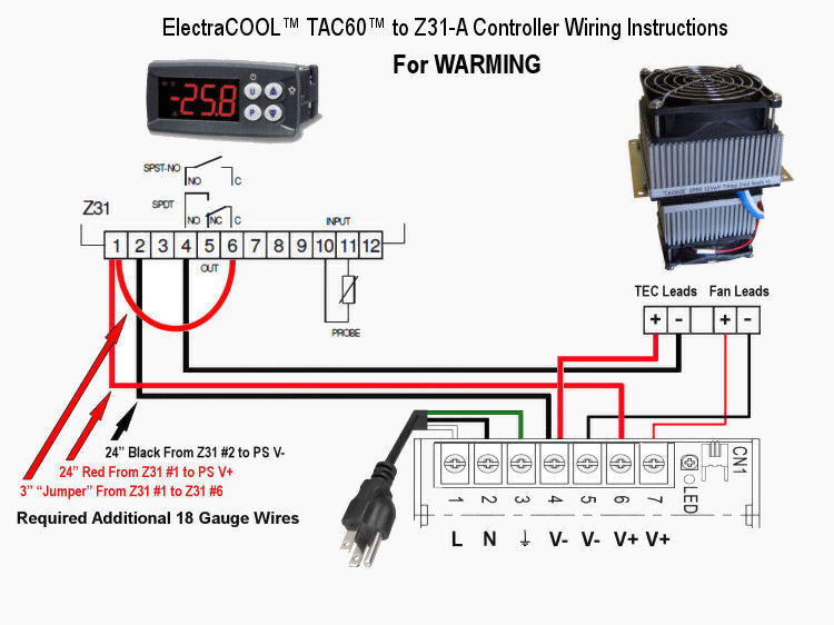
Wiring for WARMING
For warming, modify the wiring from cooling to warming, as illustrated below (to reverse polarity to the TEC/s).
Connect the black lead/s from the TE/s (heavier gauge than fan leads) to Z31-A slot 4, marked "NO" for Normally Open. Then connect the red lead/s from the TE/s to a NEGATIVE (V-) post on the power supply (to change the polarity). Make all other connections to the Z31-A and power supply, as described and illustrated below (red to + and black to -).